
A few years ago I acquired a few old IBM keyboards—that used capacitive sensing—that I wanted to get working with a modern computer. If I’d known about Soarer’s converter at the time, I probably would have stopped then and there, at least for the Model Fs. However for the 5251 and 3727 Beamsprings no converter would have existed anyway. So I read the original IBM patents for capacitive sensing, and designed my own set of USB capsense controllers.
All the code/schematics/board layouts etc. is licensed GPLv3 and available here.
Everybody knows about the famous IBM (then Lexmark, and now Unicomp) Model M buckling spring “clicky” keyboards. Much has been written about their tactile and auditory feedback, incredible robustness, and benefits to typing accuracy and ergonomics. What are often forgotten are the keyboards that preceded the Model M.
What makes them interesting is how in many respects they’re even nicer to type on than a Model M; and that they have the unusual (in modern times) feature of using capacitive switching, instead of ordinary so-called ohmic switching (i.e. touching two contacts together). This means, in theory, that they should last even longer than the Model Ms, along with reducing key bounce etc.
First came the Beamspring keyboards; a 1970s attempt to reduce costs from using converted Selectric typewriters as terminals. The Beamsprings were massive and in many cases were constructed almost entirely out of steel.
Nobody would argue that they were pretty, although the more colourful keyboards scrub up a bit better.
What they do offer is possibly the nicest key-feel you’ll ever come across this side of a Selectric. Most were fitted with large 8.5V solenoids, which acted to give the operator extra feedback; the result is even closer to a Selectric.
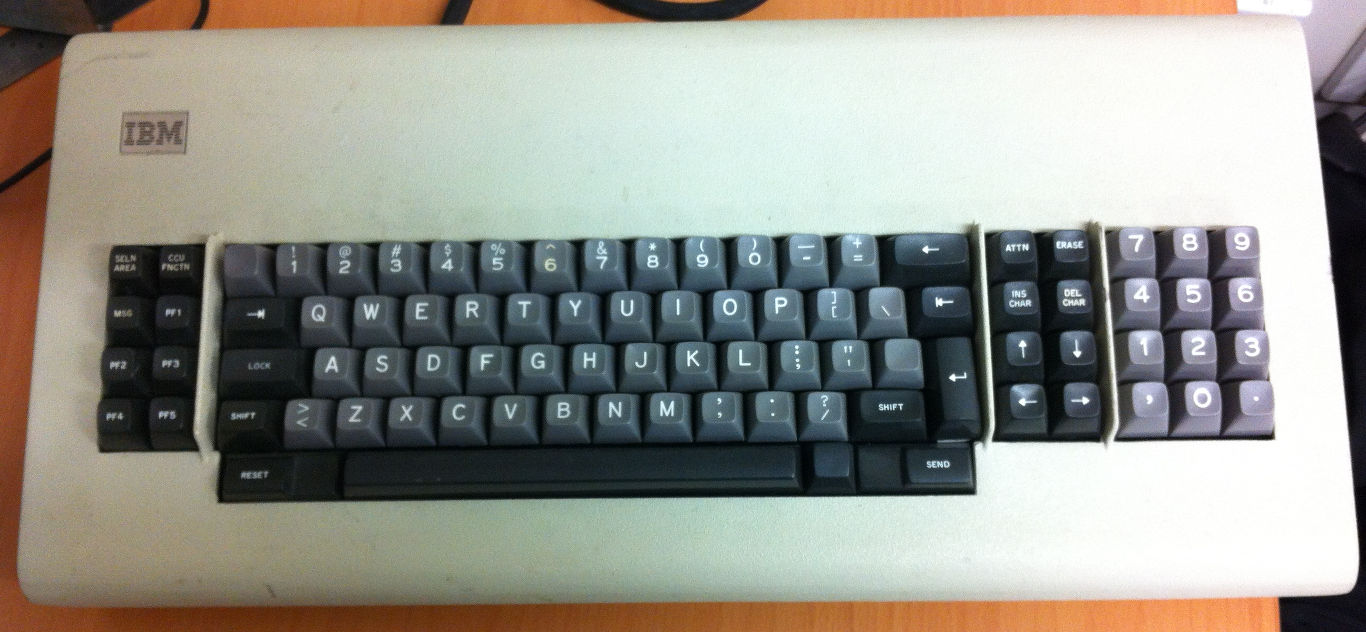
The Model F was introduced, again, as a cost-saving measure; the Beamsprings were cheaper than a Selectric, but still cost what would be four figures in today’s dollars.
They look awfully similar to the Model Ms that came later, and use basically the same technology, the buckling spring. However, like the Beamspring, it again uses capacitive sensing instead of a membrane with physical contacts. It feels lighter and smoother, and the actual “click” feels sharper and much more defined. One interesting characteristic is the musical “pings” released; each key has a slightly different pitch.
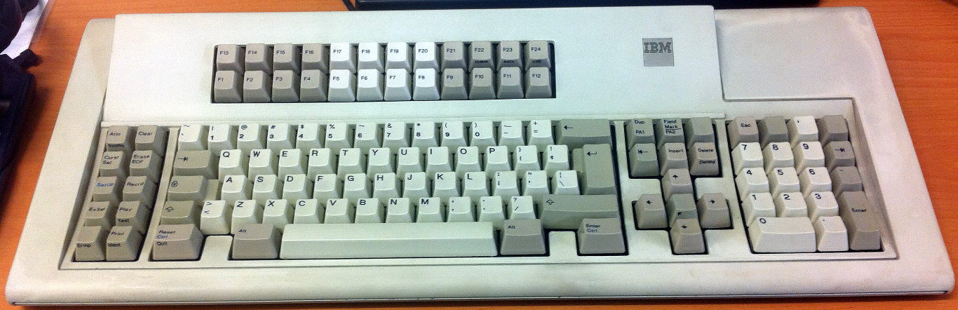
Like the Beamsprings, they came in a huge number of different sizes, from the massive 122-key terminal board (pictured above), to the tiny 62-key 6019284 keyboard for the 4704 banking terminal.
What does capacitive sensing mean?
In a normal keyboard, each key is an ordinary switch. Things get fancy because they’re placed into a matrix, but forget about that for now.
Ohmic switches are easy to read (put voltage on one end, check if it comes out the other), but have some drawbacks. For a start, the contacts have to be nice and clean. Oxidation can cause them to malfunction, the contacts can physically wear out, and a reasonable amount of force is required to make sure good electrical contact continues to happen.
One alternative is capacitive switching. Each key switch is essentially a small capacitor. When the key is up, the capacitance will be one value, and when it is down it will be another. In the Beamspring, for example, the capacitance of a pressed key is (very!) roughly 4pF; an unpressed key is ten times that. The Model F has larger values of capacitance, and it’s actually the pressed key that has higher capacitance.
While much harder to “read” (especially for 128 keys many times a second), capacitive sensing has many advantages over ordinary ohmic switching. In IBMs implementation, you simply have two unconnected pads on a PCB; the mechanical switch only moves a chunk of plastic infused with carbon closer or further away as the key is switched. In both the Beamspring and Model F the plastic bit actually touches the PCB itself, but it doesn’t have to press against it very firmly, and actual contact and wear to the pads is prevented by hard-wearing soldermask.
IBM covers a lot of the juicy bits of their implementation in U.S. Patent #4,274,752. There’s also some interesting diagrams in U.S. Defensive Publication US T904,008 I4.
The USB side of a keyboard controller is easy these days; choose one of the USB-capable Atmel 8-bit AVR ATmegas (yes I know you can use V-USB, but it’s far easier to do things by the book). Then you grab a copy of Dean Camera’s excellent LUFA USB framework.
The hard part in this case was always going to be the capacitive sensing.
There are many ways to sense capacitance. One of the most popular and widely-used is to use the capacitor as part of an oscillator; as the capacitance changes, the oscillation changes frequency and that’s relatively easy to measure.
The problem with that method for a keyboard having up to 128 keys (on a 16x8 matrix keyboard) is you simply can’t sense things quickly enough, at least not without using really high frequencies that your poor 16MHz ATmega32U2 wouldn’t keep up with. Remember, to sense keypresses quickly enough on a keyboard, you will probably need to scan 50 times a second; better yet, 100Hz or more. Taking the frequency-measuring approach means you have about 150µs per key, not including the rest of the stuff you have to do with a keyboard controller (like assign key positions to scancodes and send them to the PC).
It took me a while to figure out a nice way of doing it; the real breakthrough came when reading the IBM patents carefully through the “patent-speak”, and paying attention to a particular formula listed in one of them: .
Capacitors are boring when you feed them a steady signal. If you feed them a changing signal, they do cool stuff.
These two pages do a good job of explaining how you can integrate and differentiate (yes, just like high-school calculus) signals using a capacitor.
The formula above () is the differentiation formula of current through a capacitor. What it means is, the current through a capacitor is proportional to the change in voltage over time multiplied by the capacitance itself.
In the picture below you can see the effect of putting a sharply-rising pulse into one end of a capacitor; you get a spiky waveform out the other side:
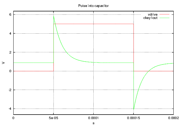
Where the input pulse (vdrive) rises quickly you get a steep level of current in the capacitor. Once the pulse has finished rising, the current slowly drains out (through a resistor in the SPICE simulation). When the pulse quickly drops back to zero, you get a mirror image negative spike.
The nice thing about this pulse is that, as mentioned above, it is proportional not just to the rise/fall time and voltage level of the pulse, but it is also proportional to the actual amount of capacitance. That means for a small capacitor, you will have a small spike, and for a large capacitor you will have a big spike. This is illustrated below, with a trace coming out of another capacitor one-tenth the size:
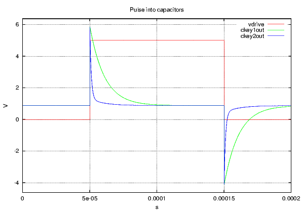
In reality, with the IBM keyboards, the sorts of spikes you get are much smaller than illustrated; around 100mV is typical.
This approach is perfect for a keyboard. We don’t actually care how much capacitance there actually is; we only care if it’s a little bit or a big bit—whether the key is up or down. Doing things this way we can set a threshold for whether a key is considered up or down, and scan the whole keyboard very quickly.
This sort of difference is something which is very measurable with a comparator, as long as you set the reference threshold correctly1 . Even the bog-standard old LM339 does a perfect job. The only worry is the negative spike; in theory (if you take the datasheet as gospel) this could cause damage to the comparator. That’s easily solved by biasing the caps up above 0V with a resistor divider (R2 and R3 below).

Of course with the resistor divider, you can overwhelm the tiny charge in the capacitor before you have a chance to measure it with the comparator, so it’s wise to put a resistor between the cap and the divider to add a bit of impedance (R1 above). You also have to be careful of having too high impedance; it’s possible for the caps to retain charge between scans (remember we’re pulsing each cap hundreds of times a second), and that can throw off the measurements; about 100K means the caps drain fast enough between scans, but retain enough charge to read with the comparator at our leisure.
Of course you can pulse the caps with whatever you like. A microcontroller GPIO pin would be perfectly suitable. However, the beamsprings have 23 columns that need pulsing; this is a lot of microcontroller pins to dedicate, especially when we only need to pulse one at a time.
Shift registers are a good fit then; the ’595 works well. I chose the 74AHC595; they’re quicker than the 74HC version, with faster rise times and outputs that hold their voltage up a bit better under higher current. Remember, the output spike from the capacitor is proportional to rise time and pulse amplitude, so the higher voltage, and the faster it rises, the better signal we get to measure. I don’t know if 3.3V logic would work quite so well here.
Putting the above concepts together, for a Beamspring keyboard controller we end up with this:
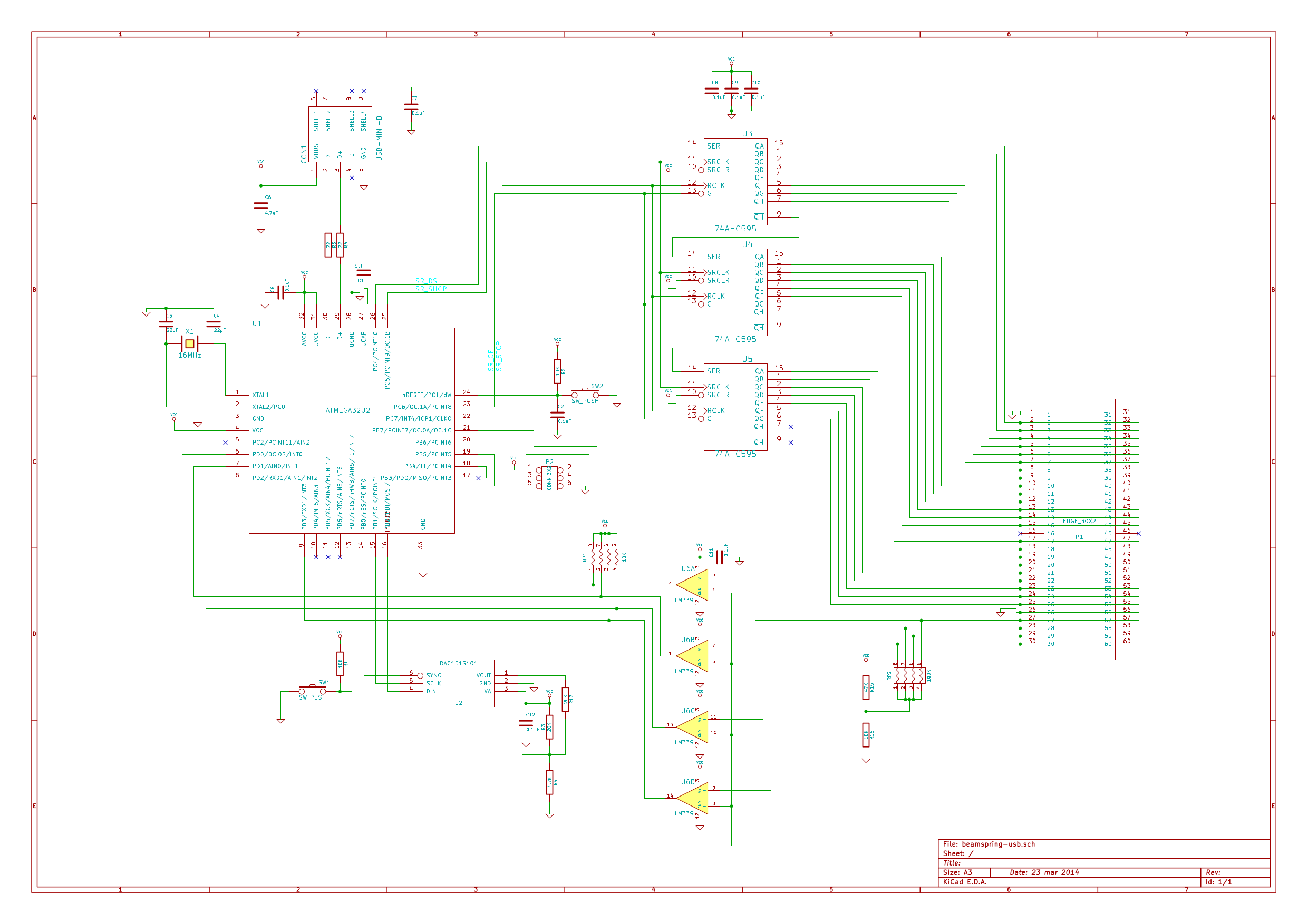
The Beamspring has a 23x4 matrix—23 columns and four rows. That means we can use a single LM339A quad comparator for the four rows, and pulse each column in turn using three 74AHC595 shift registers chained together.
We use a DAC101S101 digital-to-analogue converter to set the voltage threshold for the comparators. Using a fixed reference isn’t really viable, as tolerances between the keyboard and the controller mean calibration will always be necessary. Using a DAC means we can auto-calibrate; and, if an individual keyboard had keys that were vastly different from each other, the DAC can be quickly changed over the SPI interface to a new value.
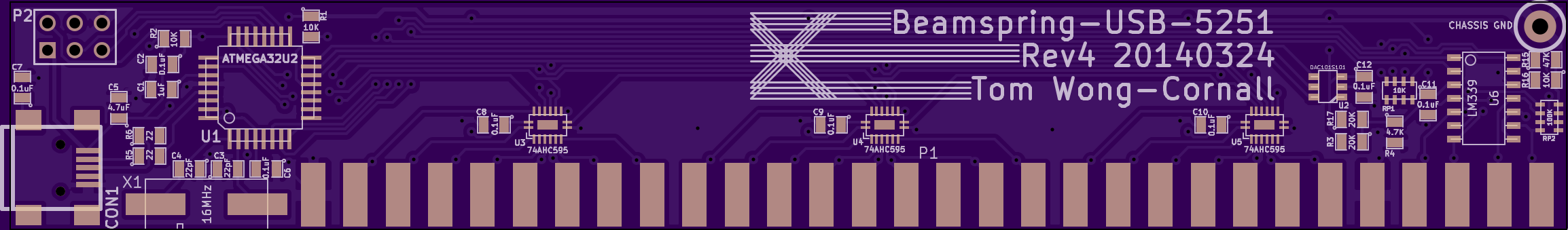
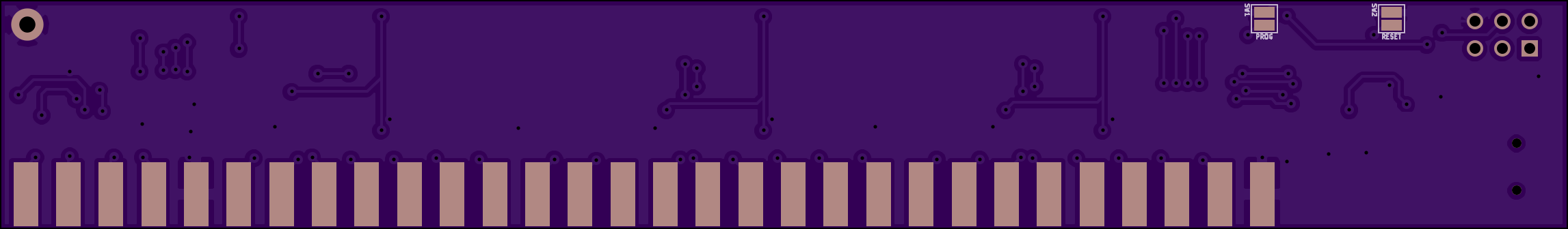
Pictured below is an OSH Park render of Revision 4 of the design. There’s been a few tweaks to the layout to ease assembly (the tiny DHVQFN16-package 74AHC595s are great for reflow, and ease the layout tremendously), and a shift to a different DAC and things like resistor packs to save time, but it’s essentially the same board. A revision 1 board is still in one of my Beamsprings.
And here’s a picture of an assembled board sitting in my 3727:
You can see the big ugly 30-column 3.96mm-pitch edge connector. These are a little hard to find; eBay is the best bet (search for stuff like 805 series 3.96mm). The ground wire is necessary, otherwise there’s no physical connection between the controller’s 0V and the chassis ground, and it’s much more prone to interference and drift.
The firmware was written with avr-gcc and (as mentioned above) uses the LUFA framework for USB.
The scanning then is pretty simple. Load the shift registers so a single output is high, strobe them so it’s live, then check the row inputs to see what the comparators are saying, reading all four rows at once.
Auto-calibration is just a case of iterating through DAC values for the voltage reference until all the keys that should be up stay up, and all the keys that should be down (there’s normally a few sense pads for this purpose hidden within the matrix) stay down. Iterating through these values is sped up a bit by doing a sort of partition search to narrow the range down quickly.
Later on I got clever and added support for ??; in addition to the normal base layer, there are three additional function layers that can be selected by assigning function keys.
For the USB side of things, I started off reading the LUFA keyboard demos before getting progressively more and more complex, learning way too much about USB HID in the process.
The keyboard actually appears as a composite device. The first interface is just the boring old standard keyboard interface. This is a “boot-protocol” interface and is very rigidly defined; you send 6 keys as 6 bytes (set some of those bytes to nulls if there’s not 6 keys pressed), a byte for modifiers (L/R Shift/Meta/Alt/Ctrl etc. as bits), and the host sends you a byte with a bitmask LEDs the host wants you light up in return.
The second interface is one of those horrible USB hacks you see everywhere; bastardising a “vendor protocol” HID interface to do stuff that isn’t technically HID. This lets the util software talk to the controller without having to open the keyboard and press buttons to reboot it.
The third interface actually took some head-scratching. All the cool keyboards these days have NKRO, and despite it probably being relatively pointless I still wanted to implement it.
The NKRO interface itself isn’t hard in theory. Some manufacturers do crazy stuff like pretend to be a bunch of keyboards which each have a standard 6-key interface. However a simple understanding of the HID spec and HID descriptors leads you to realise you can implement an NKRO interface simply by using a bitmap image of keycodes instead of individual bytes. This the same way the standard boot-protocol keyboard interface sends you the LED states. For scancodes, you tell it the first bit in the image corresponds to scancode 0, and the last bit in the image corresponds to scancode 128 (or whatever).
This is trivial to implement, and it turned out Soarer’s converter already did the same thing, and the only remaining gotchas were with some OS’s interpretation of the results; on Linux, some USB scancodes get remapped to the same kernel scancode, and they can cancel one another out. To solve this I copied Soarer’s solution of inserting dummy “padding” bytes where these dodgy scancodes were.
The full set of descriptors can be seen in all their shouty caps-lock here.
The only remaining drama with the NKRO interface concerned boot-mode compatibility. The standard boot-mode keyboard interface is designed so something really dumb like a BIOS can use a USB keyboard without having to worry about HID descriptor parsing etc. The BIOS just looks at the first few parts of the descriptor, sees “boot-mode keyboard protocol” and starts using it as such. Obviously our NKRO interface will not work here.
An intelligent OS on the other hand looks inside the descriptors to see exactly what they’re telling it, and can use our fancy NKRO interface just fine. However, every OS I tried simply saw the boot-mode keyboard interface first, and didn’t bother with the second keyboard interface—or worse, got confused by two keyboards telling it different things on the same device.
The solution, then, is to keep the boot-protocol interface, still advertise that it’s a boot-protocol keyboard interface, but mark all its contents as meaningless padding. The BIOS doesn’t read that part and uses it as is. The OS, however, skips over it and uses our nice fancy NKRO interface.
The really nice thing about NKRO on these capacitive boards is that you
actually get proper NKRO; no ghosting or need of blocking. As each switch is its
own capacitor, you don’t get the ‘short-circuiting’ effect of ghosting you do with a
normal keyboard. It’s lots of fun to open up xkeycaps and mash all the keys you
can—and see them all light up.

Naturally we need some way of getting scancodes and voltage references into the keyboard; changing source code then recompiling to do this sort of thing is fine for my window manager but not so good for my keyboard.
Instead, we use the above generic interface to send data to and from the keyboard. I made sure to put a function in here to allow jumping to the pre-flashed USB DFU bootloader without having to open up the keyboard to press buttons.
I used Qt and the nice and clean HID API library to write a quick-and-dirty
GUI util. This lets us recompile easily for to run on Windows and Mac OS X as
well as Linux.
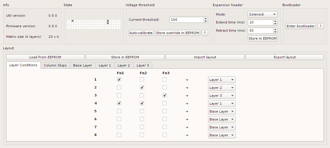
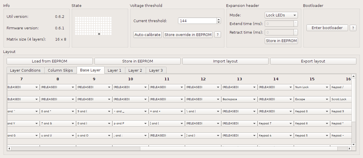
It shows keyboard state (very handy when setting up a board for the first time manually, not knowing which keys are sense pads for autocalibration), along with allowing setting the voltage reference manually.
There are many, many combo boxes for setting up scancodes on each
layer; in the picture above you can see the setting up of function key
combinations for layer selection.
The Beamsprings have been going pretty well for a little while now; I’ve built a few controllers for people, and a handful of people have soldered them themselves. There has been some more development done, however.
The Beamsprings, as described above, were often fitted with solenoids (because they weren’t loud enough?). Firing the solenoid would seem like a simple task, except for the following:
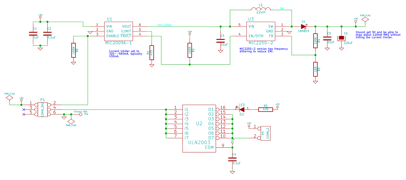
A capacitor charge pump isn’t going to do that, so I designed a little boost converter using the MIC2250 to give 9V. I was worried about switching noise playing havoc with the capacitive sensing, so the MIC2250 is a nice chip; it has frequency dithering to spread the noise around a bit.
Unfortunately, SMPSs require big capacitors, and USB doesn’t like that. A maximum of 10µF is allowed across USB power rails to avoid voltage sag on other devices when you plug a new device in. I figured I needed at least 22µF on the input of the SMPS, and that much again on the output (plus 220µF of bulk electrolytic capacitance).
Making life more difficult is the fact you are technically not allowed to draw your full 500mA until you’ve enumerated successfully; you’re only allowed 100mA. Clearly plugging in a controller fitted with one of these solenoid drivers was going to draw far more inrush current than that.
These sorts of problems are pretty common apparently, so there’s plenty of current-limited load switches around; I chose the MIC2009A. It limits inrush current gently, and allows setting a maximum current during run with a resistor. I only turn the switch on after the USB interface has enumerated and we know we can draw all 500mA.
A common ULN2003 relay driver is complete overkill (but very cheap) for switching the 9V, and works nicely.
The result is this circuit:
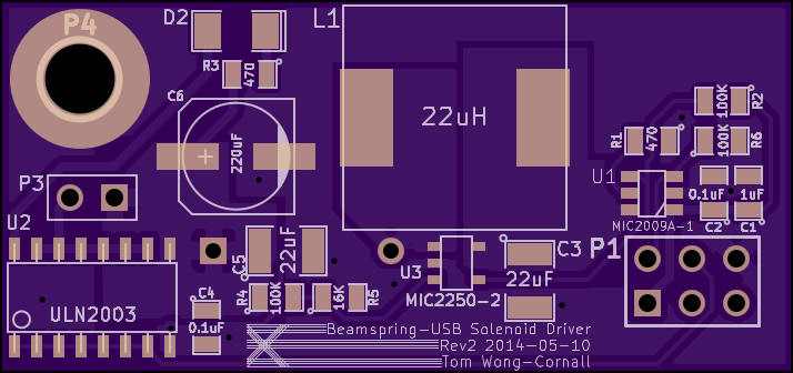
Which all fits nicely onto a little 45x21mm board:
The first stab at this didn’t work properly though. When the solenoid was fired, the boost converter rushed to fill the output caps again, struggling to hold the solenoid in at the same time. This tripped the MIC2009A’s current limiter, causing it to enter linear mode, generating way too much heat. The MIC2009A rapidly hit the 135°C temperature limiter, shutting down. Meanwhile, the SMPS output caps drain entirely. As soon as the MIC2009A cools down enough to turn back on, the SMPS sucks down a devastating amount of current again to try and restore 9V output, kicking the whole sequence off again. It would take maybe 10 or 15 seconds to finally recover from this thermal cycling, even well after releasing the solenoid.
The solution to that was to use the fault output of the MIC2009A (which turns on when it begins current-limiting) to implement a crude switch-mode current limiter. The open-collector fault output is wired to the MIC2250’s enable input. When the output turns on (goes low), it pulls the active-high enable input low and the SMPS turns off. Some tens of milliseconds go by and the fault output goes off again, allowing the SMPS (which has a soft-start feature) to turn back on. Once the solenoid has been released, everything immediately returns to normal.
This had to be implemented on the Rev1 boards with a dodgy green wire and
some kapton tape:

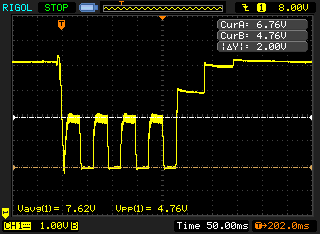
The fault output is a fairly low frequency output (note 50ms div!), which
means there’s tonnes of hysteresis. However it works nicely for our purpose:
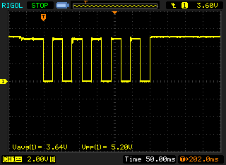
Here’s a trace of the actual 9V output, being pulled down to 5V as the SMPS
shuts off, charging up a little bit before being shut off again. The solenoid holds
in fine at 5V (it just moves sluggishly initially), so this is no problem.
It’s all a little crude, but we get the result of a nice snappy solenoid with current requirements well within USB spec, and no heat.
Given that the same basic capacitive key technology was used on the Model F buckling spring keyboards, I decided a controller was needed for them too (tiring of using an adapter to convert my PC-AT keyboard to USB).
This wasn’t too painful; the biggest issues were around mounting points (which I’m still solving now for Rev2 with the little 62-key 6019284 keyboards), and the increase to 8 rows.
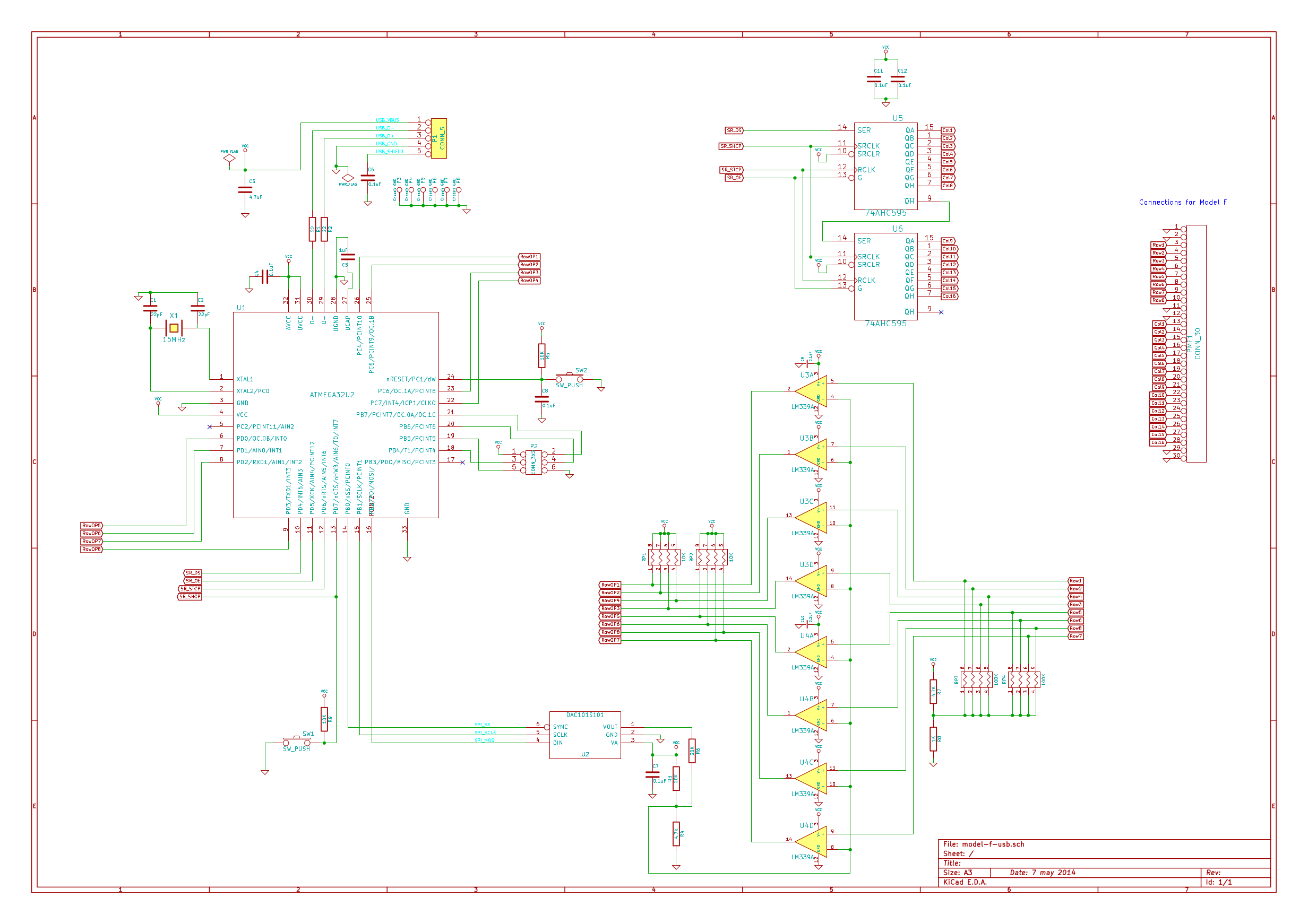
Adding the extra rows and juggling things around a touch produces this:
You can note one of the shift registers can be dropped (only 16 columns), and we
need an extra LM339A. Aside from that, pretty straightforward—not many pins
left on the ATmega32U2 though!
I was worried about possible variances between the two LM339As, but luckily they seem close enough to ignore.
With the extra four rows, I found that on a pulse the resistor drain divider (R7 and R8) was getting knocked around too much, and was causing scan issues when a key could be “shadowed” by another pressed key in the same row but previous column. Dropping R7 and R8 down to 4.7K and 1K (from 47K and 10K respectively) improved things here, as did increasing the delay between columns somewhat. We can still achieve 500Hz scanrates comfortably enough however.
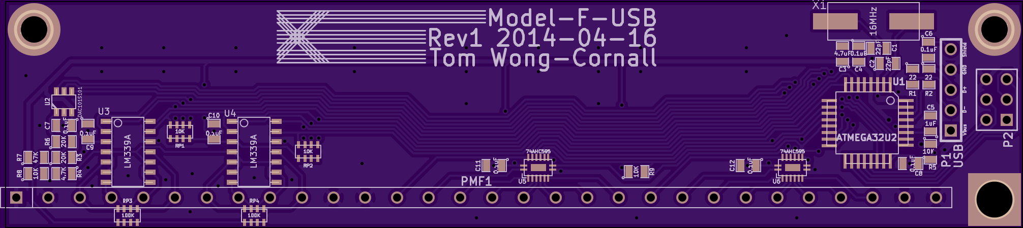
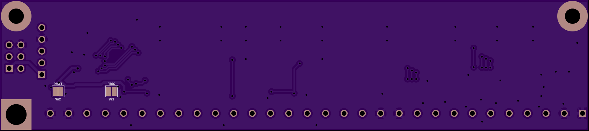
Soldered up they look like this:
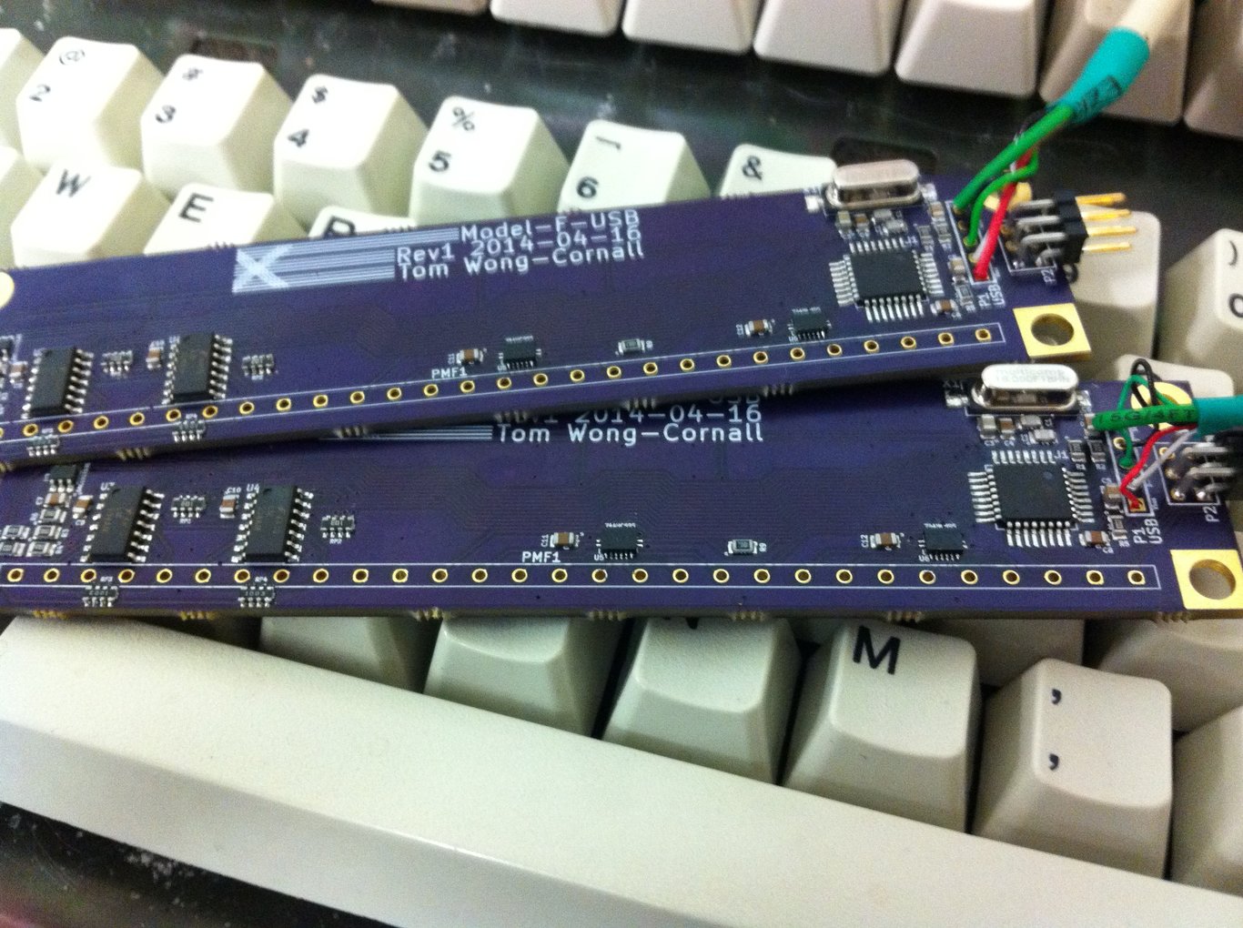
And installed (desoldering the old ribbon cable is no fun!) in my PC-AT, the
original controller shown for scale:
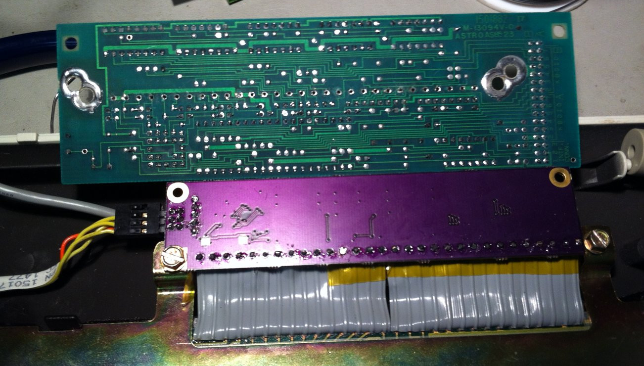
It works pretty well. We even get LEDs; the above picture shows the LED ribbon cable coming in from the left to plug into the “expansion header” that I put in originally to connect to the solenoid driver board. A few pins needed juggling around in the connector but it works fine.
The tiny 4704 keyboards have piezo buzzers installed; these can be fired using the same expansion header by pretending there’s a solenoid driver board attached. I don’t know how long I could stand the beeping for!
The Displaywriters (see here and here) were a bit of an oddity. They came right at the end of Beamspring production, and after a little while they kept selling the same system with a Model F version.
They must have been designed alongside Model Fs, as the matrix bears far more resemblance to a Model F than to a Beamspring; although it shares the 30-pin 3.96mm edge connector, it has 8 rows just like a Model F.
For some reason, unlike all other keyboards, they placed 4 rows on the left-hand-side of the connector, 12 rows in the middle, and another 4 rows on the right-hand-side. The rows are interleaved (for noise immunity?).
I won’t bother showing you the schematic, as it’s basically identical (apart
from connector pinout) to the Model F. The PCB layout becomes a little
interesting though. I kept the single DAC (U2 below), but placed it in the middle
of the controller and had to run relatively long traces to each comparator:
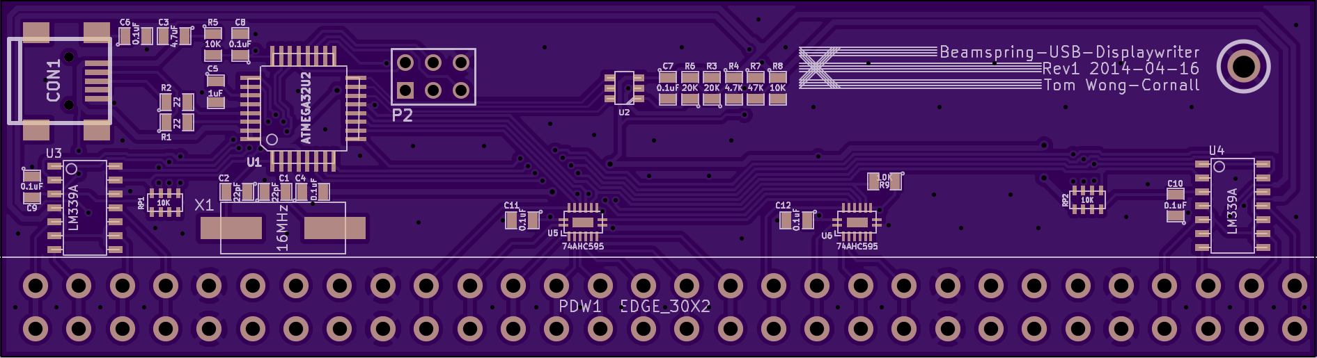

The finished board has a nice symmetry to it. The connector has to be
mounted vertically rather than on-edge, as the Displaywriters have plenty of
height room but not enough depth to mount it the same as the other
Beamsprings.

The basic principle is working well, but there’s still a few things I want to add:
These will have to compete for space with all the other projects piling up.
I’m currently running a group-buy for a batch of these boards over at Deskthority and Geekhack to see if I can’t batch a few board builds together, rather than the usual one-offs when somebody emails me. If you’re interested, send me an email.
Alternatively, as I keep repeating (but nobody seems to want to hear), these are fully open-source, so grab a copy of the Kicad PCB and firmware from here, or order a pre-Gerbered PCB directly from my profile on OSHPark. If you do build your own, I’d love to know about it, so drop me an email if you do!